 English
  Lietuvių
  Русский
 Expert Logger
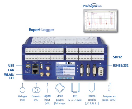
Expert Logger is a new generation of data loggers. It combines the latest communication technology with advanced measurement technology, and is based on FPGA technology to make it especially powerful. It can process up to 46 analog input channels at both low and high rates of sampling. Measurement data can be accurately acquired, independently stored and transmitted to the internet or a PC for evaluation via USB, LAN, WLAN or LTE.
With an OPC UA interface
OPC UA is becoming an increasingly established protocol and when used with the Expert Logger devices, measurement acquisition, monitoring and test stand automation applications can be made ready for open data exchange data in accordance with Industry 4.0/Internt of Things.
Both OPC UA servers and clients have been integrated into the Expert Logger devices to enable fast, easy and barrier-free data exchange with sensors and sub-systems also supporting OPC UA.
Many products such as frequency converters, controllers and regulators have already fully integrated OPC UA. The opportunities provided by OPC UA have been identified within the measurement and sensor technology sector with several sensors and actuators now available with OPC UA interfaces.
In addition to OPC UA, Expert Logger devices are also equipped with PROFIBUS, ModBus, CAN-Bus and serial interfaces for sensor and field level connections.
Operation made simple
Sensors are connected via plug-in screw terminals and a chart clearly shows how channels are arranged. Users always have a good overview of the channels despite their high density. Each set of four terminals can be configured as two differential inputs to measure voltage, currents, thermocouples, or to take measurements from a 4-wire RTD.
Configuration - fast and easy
The Expert Logger is simple to configure from a PC. These settings remain stored within the Expert Logger even when disconnected from the power supply. The device settings can also be read out and stored on a PC and analysed offline without the need for a connected Expert Logger. The offline configuration settings are then simply read into the device when connected. The software used for configuration is simple to operate to let users fully focus on their measurement tasks.
Intelligent signal processing
Signal processing using internal software channels significantly simplifies measurement tasks. Flexible calculation channels enable measurement data to undergo further computation and recording. Integrators directly calculate volumes or quantities from time related measurement data such as mass and discharge flow rates. Limit values can monitor measurement data and be used to switch digital outputs or automatically send emails. Complex signal processing is possible using pulse counters, stop-clock functions and operating-hours counter. Averages can be calculated and recorded as time-weighted or moving. The Expert Logger‘s software channels clearly set it apart from other loggers and make it very popular among users.
Functions of Expert Logger
Following is a list of the main features of Expert Logger.
Sensor connection
Universal analog inputs (mV mA, TC, RTD)
Digital inputs and outputs
Plug-in screw terminals
Serial and SDI12 interfaces
SDI12 interfaces for environmental sensors
Serial RS232 ports and a RS485
Configuration of individual ASCII protocols
Battery and rechargeable operation
Independent operation possible with batteries orrechargeables
Minimal energy consumption via a sleep function
User-defined wake and measuring intervals
Internal data storage
4 GB of internal data storage for up to 125 million measurement values
Time stamps to msec resolution
Data read out via LAN, WLAN or USB interface
External data storage
Data recorded to external storage media (USB, NAS)
PUSH function to send measurement data to theinternet
Event-triggered recording with pre and post histories
Remote monitoring
WLAN link to PCs and mobile devices
Optional LTE / UMTS / 4G integrated modem
Automatic notification via email or text messaging
PC and field bus interfaces
LAN and USB interface to a PC or network
CAN-Bus interface for reading / writing identifiers
Field bus interfaces PROFIBUS DP, Modbus
Monitoring functions
Monitoring and data logging in a single device
Limit value setting for any sensor signal or calculationchannel
Controlling digital outputs with user-defined triggering
Logging of pictures from webcam by external trigger
Signal processing
Averaging (middle, min, max, RMS values)
Integration of time signals into volumes, masses or working values
Computational functions (basic functions, polynomial, trigonometric ...)
Touchdisplay
The touch display enables users to configure the Expert Logger‘s basic settings such as the IP address and network mask. The display also simultaneously shows selected measurement data. The display operates via either touch or an external USB mouse.
Universal, communicative, reliable
Expert Logger is available in three versions which differ only in the number of analog and digital inputs they can process. All Expert Logger devices are equipped with internal 4 GB memories that can independently store up to 125 million measurement values with date and time stamps to msec precision. Storage capacity can be extended as required via external USB or LAN storage devices (NAS). An integrated, energy-saving “sleep function“ automatically switches off the device during breaks in measurement acquisition. The Expert Logger operates with standard batteries, rechargeable batteries or solar units.
Precision measurement is ensured through the use of a 24-bit converter. Voltages can also be precision recorded to the μV range. All channels are galvanically isolated to suppress earthing loops and the tried and tested input circuitry protects the device against voltage spikes. Electromechanical components are avoided (relays multiplexer), and the device operates noise and maintenance free. Delphin‘s patented analog inputs guarantee years of reliable measuring work.
Expert Logger accessories
Rechargeable pack for energy independent operation
External data storage
UMTS / LTE module
WLAN module
Measurement data analysis included
To make it as easy as possible for users to operate the Expert Logger, the powerful ProfiSignal Go software is included free with delivery. ProfiSignal Go enables users to portray measurement data online and offline and to carry out detailed analysis. The software can portray the Expert Logger‘s measurement data in trends. Users can choose between y(t) or y(x) diagrams as well as a range of other analysis diagrams. ProfiSignal Go is especially intuitive to make it highly user friendly.
A range of options
Online / offline analysis and diagnosis of measurement data
A range of trend formats y(t), y(x), digital signal analysis
ASCII / CSV / TDM data exporting
Output or export of trends as EMF files
Analysis using cursor functions
Offline data evaluation is easy and quick to perform. The software also enables fast ASCII exporting of the measurement data for MS Excel™, or conversion into TDM format.
Our customers tell us that it is a pleasure to use ProfiSignal Go.
Technical specifications
| Expert Logger | |||
| Device type | 100 | 200 | 300 |
| Analog inputs (mV, mA, TC) | 16 | 32 | 46 |
| Appropriate for RTD´s | (8) | (16) | (23) |
| Total sampling rate | 1000 Hz | 2 groups of 1000 Hz | 3 groups of 1000 Hz |
| Voltage / current measurement range | ± 156 mV .. ± 10 V / 0 .. 20 mA, 4 .. 20 mA, free | ||
| Current reference for restistance measurement | None, 100µA, 200µA or 1 mA software switchable | ||
| Resolution / input impedance | 24 bit / 1GΩ | ||
| Reference junction | yes / 2 | yes / 4 | yes / 6 |
| Withstand voltage / galvanic isolation | ± 100 VDC / ± 400 VDC to PE | ||
| Channel to channel | ± 100 VDC / ± 400 VDC | ||
| Digital frequency inputs | 4 to 8 | - | |
|
Input signal |
low: 0 .. 1.2 VDC / high: 5 .. 100 VDC-3.5 mA | - | |
| Measurement range, frequency inputs / Broadcounter | 0 .. 200 KHz / 64 bit | - | |
| Galvanic isolation | yes, up to ± 400 VDC to PE | - | |
| Digital outputs (also PWM) | 4 to 8 | - | |
| Max. switching voltage / current | 50 V / 3 A | - | |
| PWM basic frequency | 5 Hz to 10 kHz | - | |
| Pulse-width modulation / resolution | 1:1000 | - | |
| Galvanic isolation | yes, up to ± 400 VDC to PE | - | |
| Digital voltage reference | 1 | - | |
| Current | up to 140 mA | - | |
| Voltage | 5 VDC | - | |
| Short circuit proof | yes | - | |
| Galvanic isolation | yes, up to ± 400 VDC to PE | - | |
| Data storage | |||
| Data storage internal | 2 .. 14 GB / ca. 30 million measurement values to GB | ||
| Data storage external | USB, NFS, CIFS, (S)FTP | ||
| Interfaces | |||
| Sensor bus SDI12 | 1 | ||
| Physical equipment COM 1 / COM 2 | RS485, 9-pole Sub-D plug, DIN EN ISO 19245-1 | ||
| Physical equipment COM 3 | RS232, 9-pole Sub-D plugs | ||
| LAN | 1 x 1000Base-TX, 1 x 100Base-TX | ||
| WLAN (optional to WWAN) | 802.11b/g/n | ||
| WWAN (optional to WLAN) | UMTS, LTE (configuration, real time data, email) | ||
| USB | Device 2.0 low / full / high speed / Host 2.0 low speed | ||
| CAN 2.0 / PROFIBUS | 2x / 2x, max. 12 Mbit | ||
| Protocols | |||
| PROFIBUS | DPV1 Slave / passive sniffer | ||
| RS 232 / 485 | Modbus RTU, SCPI, ASCII | ||
| CAN | CAN RAW | ||
| TCP/IP | Modbus TCP, OPC UA | ||
| General technical information | |||
| Dimensions / weight | 210 x 80 x 125 mm / 750 g | ||
| Fixing | Rail mounting DIN EN 60715 or screw fixing | ||
| Signal connections | Plug-in screw terminals, max. 1.5 mm2, 96 in 2 rows | ||
| Temperature range | -20 .. 60 °C | ||
| Power supply | 12 .. 24 VDC / ± 10 % | ||
| Power input – normal mode | max. 10 Watt | ||
| Power input – sleep mode | 5 mW-12 V, 10mW-24V | ||